|
The Return and Update button accepts the section.
|

|
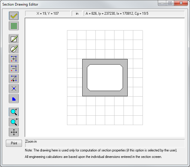
The Drawing Properties Settings button allows you to edit the drawing limits, grid and snap settings. This button activates the Drawing Properties screen.
|

|
The Add New Polygon button starts the mode to draw polygons composed of straight lines. Left-click to add sides; a node will appear. Right-click on the last node to close the drawing.
|

|
The Add New Circle button is used to add a circle to your drawing. First, click the location where you want the center of the circle. Move the mouse until the desired radius is reached and click again. If a circle is drawn completely inside another polygon, then it is treated as a cut out (or hollow).
|

|
The Add Nodes button is used to add nodes to the polygon. All nodes that comprise the polygon and circles will become visible when this button is selected. To add additional nodes, click anywhere between two nodes. To add a new point between two existing points, both existing points must be visible on the screen.
|

|
The Delete Nodes button is used to delete a node on the polygon or entire circle. Clicking on this button will also display all nodes. Click on a node in the polygon to delete that node. Click on any node on the circle to delete the entire circle.
|

|
The Modify Nodes button allows you to modify the shape of the polygon. Clicking this button will display all the composing nodes for the polygon. To move a node, drag any node to another location. Left-click and hold on a node and move to desired location. Release mouse button.
|

|
This is the Show Vertex button. Use this button to display a list of vertices in a tabular format. The X and Y coordinates values may be modified for any. You can also add nodes in the section drawing and modify the coordinates as desired.
|

|
Clicking the Chamfer and Fillet button will display all the nodes that compose the polygon and circles. By clicking on any node in the corner of the polygon, the "fillet" and "chamfer" dialog box will display allowing you to select the type as "chamfer" or "fillet". You can also edit the fillet dimensions in this dialog box.
|

|
The Zoom in button allows you to zoom in on a part of the drawing. After clicking this icon, you must select the area to enlarge by holding down the left mouse button, and then dragging the pointer over the part to be enlarged.
|

|
The Zoom out button allows you to zoom out. Select an area to zoom out of by holding down the left mouse button, and then dragging the pointer over the part to be reduced.
|

|
The Pan button allows you to pan the image. After clicking on this button place the pointer anywhere in the image, hold down the left mouse button, and drag until the pan is at a desirable view.
|